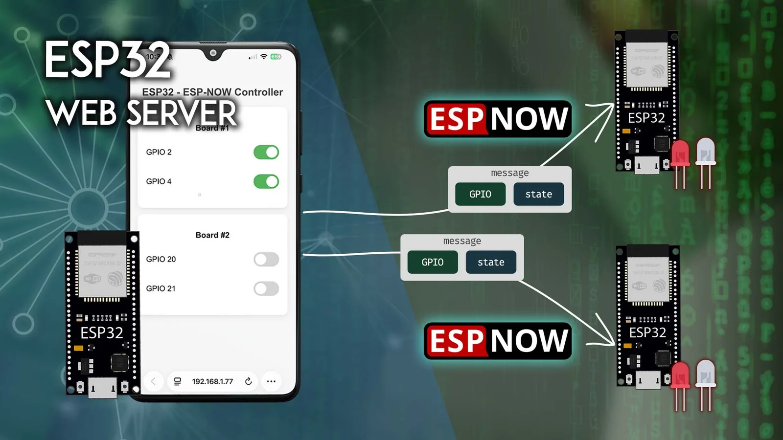
¿Te imaginas prender y apagar las luces de tres rincones distintos de tu taller desde una sola pestaña del navegador, sin router de por medio para el tramo final ni una nube externa? Eso es exactamente lo que resuelve este proyecto: un ESP32 "controlador" levanta un servidor web con interruptores tipo switch, y cada vez que tocas uno, dispara un mensaje ESP NOW directo a la placa ESP32 que corresponde para mover su GPIO.
Al terminar vas a saber leer la dirección MAC de cada placa, armar el circuito con LEDs, cargar el firmware receptor y el firmware controlador, y entender el detalle más fino de este montaje: cómo el controlador confirma la entrega de cada comando y revierte el switch en pantalla si el mensaje no llegó. Trabajamos con dos receptores, pero el diseño escala a tres o más placas cambiando muy poco código.
Cómo funciona: controlador, receptores y confirmación de entrega
En vez de ir paso a paso a ciegas, conviene tener el mapa completo antes de soldar nada. El sistema tiene dos roles bien separados:
- Placa controladora (sender): aloja el servidor web y actúa como emisor ESP NOW. Muestra una tarjeta por cada placa remota, con dos switches por tarjeta.
- Placas receptoras (receivers): escuchan mensajes ESP NOW y aplican el estado recibido a su GPIO. En este ejemplo controlamos los GPIO 2 y 4 en la ESP32 #1, y los GPIO 20 y 21 en la ESP32 #2.

El controlador identifica a cada receptor por su dirección MAC, así que ese dato es la pieza clave del rompecabezas. Y hay un detalle que este montaje hace bien y que muchos tutoriales de servidores web omiten: ESP NOW entrega un acuse de recibo en el emisor. El controlador aprovecha ese callback para decidir si "confirma" el nuevo estado del switch o lo devuelve al último estado entregado con éxito. Si el receptor está apagado o fuera de rango, el switch en la web vuelve solo a su posición anterior en lugar de mentirte diciendo que la orden llegó.
Si nunca usaste ESP NOW, mentalmente pensalo como un walkie talkie entre ESP32: no necesita router para el enlace entre placas, va de MAC a MAC, y es muy rápido y liviano.
Materiales y preparación del entorno
Para reproducir el montaje de dos receptores más un controlador necesitas tres placas ESP32. El tutorial original usa dos DOIT DevKit V1 y una ESP32-S3 (por eso los GPIO 20 y 21 en la segunda placa: existen en la S3). Puedes usar los GPIO que prefieras según tu placa.

Antes de tocar código, deja el entorno listo:
- Instala el soporte ESP32 en Arduino IDE (gestor de placas). Si ya programaste un ESP32 antes, lo tienes.
- Instala dos librerías desde el Library Manager:
ESPAsyncWebServer(de ESP32Async) yAsyncTCP(de ESP32Async). Las dos son necesarias para el servidor web asíncrono del controlador.

Paso 1. Obtener la dirección MAC de cada receptor
ESP NOW enruta por dirección MAC, así que primero necesitas la de cada placa receptora. Carga este sketch en cada ESP32 receptor, abre el Monitor Serial a 115200 baudios y presiona el botón de reset: la MAC aparece impresa.

/*
  Rui Santos & Sara Santos - Random Nerd Tutorials
  Complete project details at https://RandomNerdTutorials.com/get-change-esp32-esp8266-mac-address-arduino/
  Permission is hereby granted, free of charge, to any person obtaining a copy of this software and associated documentation files.
  The above copyright notice and this permission notice shall be included in all copies or substantial portions of the Software.
*/
#include <WiFi.h>
#include <esp_wifi.h>

void readMacAddress(){
  uint8_t baseMac[6];
  esp_err_t ret = esp_wifi_get_mac(WIFI_IF_STA, baseMac);
  if (ret == ESP_OK) {
    Serial.printf("%02x:%02x:%02x:%02x:%02x:%02x\n",
                  baseMac[0], baseMac[1], baseMac[2],
                  baseMac[3], baseMac[4], baseMac[5]);
  } else {
    Serial.println("Failed to read MAC address");
  }
}

void setup(){
  Serial.begin(115200);

  WiFi.mode(WIFI_STA);
  WiFi.STA.begin();

  Serial.print("[DEFAULT] ESP32 Board MAC Address: ");
  readMacAddress();
}

void loop(){

}
Anota cada dirección, porque las vas a pegar en el código del controlador. En el ejemplo original quedaron así:
- ESP32 Receptor 1:
30:ae:a4:f6:7d:4c - ESP32 Receptor 2:
34:85:18:40:2f:cc

Paso 2. Cablear los LEDs
Cada GPIO que quieras controlar lleva un LED con su resistencia de 220 Ω en serie (ánodo del LED al GPIO a través de la resistencia, cátodo a GND). Con dos GPIO por placa y dos receptores, son cuatro LEDs y cuatro resistencias en total.
| ESP32 #1 | ESP32 #2 |
|---|---|
| GPIO 2 | GPIO 20 |
| GPIO 4 | GPIO 21 |

Paso 3. Firmware de las placas receptoras
Este sketch va en cada receptor y sirve para cualquier GPIO. Define una estructura struct_message (número de GPIO + estado) que debe ser idéntica a la del emisor, e implementa el callback OnDataRecv(): cuando llega un paquete, copia los datos, imprime lo recibido y aplica el estado con pinMode() + digitalWrite(). El loop() queda vacío a propósito, porque todo el trabajo ocurre en el callback.
/*********
  Rui Santos & Sara Santos - Random Nerd Tutorials
  Complete project details at https://RandomNerdTutorials.com/esp32-esp-now-web-server-multiple-boards/
  Permission is hereby granted, free of charge, to any person obtaining a copy of this software and associated documentation files.
  The above copyright notice and this permission notice shall be included in all copies or substantial portions of the Software.
*********/
#include <esp_now.h>
#include <WiFi.h>

// Structure example to receive data
// Must match the sender structure
typedef struct struct_message {
    int gpio;
    bool state;
} struct_message;

// Create a struct_message called myData
struct_message myData;

// callback function that will be executed when data is received
void OnDataRecv(const uint8_t * mac, const uint8_t *incomingData, int len) {
  memcpy(&myData, incomingData, sizeof(myData));
  Serial.print("Bytes received: ");
  Serial.println(len);
  Serial.print("Setting GPIO: ");
  Serial.println(myData.gpio);
  Serial.print("state to: ");
  Serial.println(myData.state);
  // Control GPIO
  pinMode(myData.gpio, OUTPUT);
  digitalWrite(myData.gpio, myData.state);
  Serial.println();
}

void setup() {
  // Initialize Serial Monitor
  Serial.begin(115200);

  // Initialize WIFI STA interface
  WiFi.mode(WIFI_STA);

  // Init ESP-NOW
  if (esp_now_init() != ESP_OK) {
    Serial.println("Error initializing ESP-NOW");
    return;
  }

  // Once ESPNow is successfully Init, we will register for recv CB to
  // get recv packer info
  esp_now_register_recv_cb(esp_now_recv_cb_t(OnDataRecv));
}

void loop() {

}
Un punto técnico que vale la pena entender: como registramos un callback de recepción con esp_now_register_recv_cb(), el chip queda "escuchando" en segundo plano y ejecuta la función automáticamente al recibir un paquete. Por eso no hace falta nada en el loop().
Paso 4. Firmware del controlador con servidor web
Acá está el corazón del proyecto. El controlador se conecta a tu WiFi (para servir la página), inicializa ESP NOW, registra a los dos receptores como peers por su MAC, y levanta tres rutas: / sirve el HTML, /control dispara el mensaje ESP NOW, y /states devuelve en JSON los estados confirmados para que la interfaz se sincronice cada 5 segundos.
Antes de compilar, reemplaza tu SSID, tu contraseña y las dos direcciones MAC en la parte superior del sketch. Con las MAC del ejemplo quedaría:
// REPLACE WITH YOUR RECEIVER'S MAC Address
uint8_t board1Address[] = {0x30, 0xAE, 0xA4, 0xF6, 0x7D, 0x4C};
uint8_t board2Address[] = {0x34, 0x85, 0x18, 0x40, 0x2F, 0xCC};
Y este es el sketch completo del controlador:
/*********
  Rui Santos & Sara Santos - Random Nerd Tutorials
  Complete instructions at https://RandomNerdTutorials.com/esp32-esp-now-web-server-multiple-boards/
  Permission is hereby granted, free of charge, to any person obtaining a copy of this software and associated documentation files.
  The above copyright notice and this permission notice shall be included in all copies or substantial portions of the Software.
*********/
#include <WiFi.h>
#include <ESPAsyncWebServer.h>
#include <esp_now.h>

// REPLACE WITH YOUR WI-FI CREDENTIALS
const char* ssid = "REPLACE_WITH_YOUR_SSID";
const char* password = "REPLACE_WITH_YOUR_PASSWORD";

// REPLACE WITH YOUR RECEIVER'S MAC ADDRESS
uint8_t board1Address[] = {0xFF, 0xFF, 0xFF, 0xFF, 0xFF, 0xFF};
uint8_t board2Address[] = {0xFF, 0xFF, 0xFF, 0xFF, 0xFF, 0xFF};

// Structure to hold GPIO state
typedef struct struct_message {
    int gpio;
    bool state;
} struct_message;

struct_message board1Data;
struct_message board2Data;

// Confirmed delivered states
bool board1Btn1 = false;
bool board1Btn2 = false;
bool board2Btn1 = false;
bool board2Btn2 = false;

// Pending messages delivery tracking
struct PendingUpdate {
  bool active = false;
  int board;
  int gpio;
  bool newState;
  bool oldState;
};

PendingUpdate pendingUpdate;

// GPIO pin definitions
const int board1Pin1 = 2;
const int board1Pin2 = 4;
const int board2Pin1 = 20;
const int board2Pin2 = 21;

// Global variables
esp_now_peer_info_t peerInfo;
AsyncWebServer server(80);

// Function to get a pointer to the state variable based on board and GPIO
bool* getStatePtr(int board, int gpio) {
  if (board == 1 && gpio == board1Pin1) return &board1Btn1;
  if (board == 1 && gpio == board1Pin2) return &board1Btn2;
  if (board == 2 && gpio == board2Pin1) return &board2Btn1;
  if (board == 2 && gpio == board2Pin2) return &board2Btn2;
  return nullptr;
}

// ESP-NOW callback function when data is sent
void OnDataSent(const uint8_t *mac_addr, esp_now_send_status_t status) {
  char macStr[18];
  snprintf(macStr, sizeof(macStr), "%02x:%02x:%02x:%02x:%02x:%02x",
           mac_addr[0], mac_addr[1], mac_addr[2], mac_addr[3], mac_addr[4], mac_addr[5]);
  Serial.print("Packet to: ");
  Serial.print(macStr);
  Serial.print(" send status:\t");
  Serial.println(status == ESP_NOW_SEND_SUCCESS ? "Delivery Success" : "Delivery Fail");

  if (!pendingUpdate.active) return;

  // Ensure the pending update corresponds to the correct board and GPIO
  bool* statePtr = getStatePtr(pendingUpdate.board, pendingUpdate.gpio);
  if (statePtr == nullptr) {
    pendingUpdate.active = false;
    return;
  }

  // Commit or revert the state based on delivery status
  if (status == ESP_NOW_SEND_SUCCESS) {
    *statePtr = pendingUpdate.newState;
    Serial.printf("State committed: board=%d gpio=%d state=%d\n",
                  pendingUpdate.board, pendingUpdate.gpio, pendingUpdate.newState);
  } else {
    *statePtr = pendingUpdate.oldState;
    Serial.printf("Delivery failed — state reverted: board=%d gpio=%d back to %d\n",
                  pendingUpdate.board, pendingUpdate.gpio, pendingUpdate.oldState);
  }
  pendingUpdate.active = false;
}

// Function to send ESP-NOW message
esp_err_t sendEspNowMessage(const uint8_t *boardMacAddress, const struct_message &message) {
  esp_err_t result = esp_now_send(boardMacAddress, (const uint8_t *) &message, sizeof(message));
  // Handle the result of the send operation
  if (result == ESP_OK) {
    Serial.println("Sent with success");
  } else if (result == ESP_ERR_ESPNOW_NOT_INIT) {
    Serial.println("Error: ESP-NOW not initialized");
  } else if (result == ESP_ERR_ESPNOW_NOT_FOUND) {
    Serial.println("Error: Peer not found");
  } else {
    Serial.printf("Error sending the data: %d\n", result);
  }
  return result;
}

// HTML Web Page
String renderHTML() {
  String html = R"rawliteral(
<!DOCTYPE HTML>
<html>
<head>
  <title>ESP32 - ESP-NOW Controller</title>
  <meta name="viewport" content="width=device-width, initial-scale=1">
  <style>
    body { font-family: Arial; text-align: center; margin: 0; padding: 20px; background: #f4f4f4; }
    h2 { color: #333; }
    .card { background: white; padding: 20px; margin: 15px auto; max-width: 420px; border-radius: 12px; box-shadow: 0 4px 12px rgba(0,0,0,0.1); }
    .switch-container { margin: 15px 0; display: flex; align-items: center; justify-content: space-between; padding: 10px 0; }
    .switch-label { font-size: 18px; font-weight: 500; }
    .switch { position: relative; display: inline-block; width: 60px; height: 34px; }
    .switch input { opacity: 0; width: 0; height: 0; }
    .slider {
      position: absolute; cursor: pointer; top: 0; left: 0; right: 0; bottom: 0;
      background-color: #ccc; transition: .4s; border-radius: 34px;
    }
    .slider:before {
      position: absolute; content: ""; height: 26px; width: 26px; left: 4px; bottom: 4px;
      background-color: white; transition: .4s; border-radius: 50%;
    }
    input:checked + .slider { background-color: #4CAF50; }
    input:checked + .slider:before { transform: translateX(26px); }
  </style>
</head>
<body>
  <h2>ESP32 - ESP-NOW Controller</h2>
)rawliteral";

  html += R"rawliteral(
  <div class="card">
    <h3>Board #1</h3>
    <div class="switch-container">
      <span class="switch-label">GPIO )rawliteral";
  html += String(board1Pin1);
  html += R"rawliteral(</span>
      <label class="switch">
        <input type="checkbox" id="b1Btn1" onchange="toggleSwitch(1,)rawliteral";
  html += String(board1Pin1);
  html += R"rawliteral(, this)">
        <span class="slider"></span>
      </label>
    </div>
    <div class="switch-container">
      <span class="switch-label">GPIO )rawliteral";
  html += String(board1Pin2);
  html += R"rawliteral(</span>
      <label class="switch">
        <input type="checkbox" id="b1Btn2" onchange="toggleSwitch(1,)rawliteral";
  html += String(board1Pin2);
  html += R"rawliteral(, this)">
        <span class="slider"></span>
      </label>
    </div>
  </div>
)rawliteral";

  html += R"rawliteral(
  <div class="card">
    <h3>Board #2</h3>
    <div class="switch-container">
      <span class="switch-label">GPIO )rawliteral";
  html += String(board2Pin1);
  html += R"rawliteral(</span>
      <label class="switch">
        <input type="checkbox" id="b2Btn1" onchange="toggleSwitch(2,)rawliteral";
  html += String(board2Pin1);
  html += R"rawliteral(, this)">
        <span class="slider"></span>
      </label>
    </div>
    <div class="switch-container">
      <span class="switch-label">GPIO )rawliteral";
  html += String(board2Pin2);
  html += R"rawliteral(</span>
      <label class="switch">
        <input type="checkbox" id="b2Btn2" onchange="toggleSwitch(2,)rawliteral";
  html += String(board2Pin2);
  html += R"rawliteral(, this)">
        <span class="slider"></span>
      </label>
    </div>
  </div>
)rawliteral";

  html += R"rawliteral(
  <script>
    function applyStates(states) {
      document.getElementById('b1Btn1').checked = states.b1Btn1 || false;
      document.getElementById('b1Btn2').checked = states.b1Btn2 || false;
      document.getElementById('b2Btn1').checked = states.b2Btn1 || false;
      document.getElementById('b2Btn2').checked = states.b2Btn2 || false;
    }

    async function loadStates() {
      try {
        const response = await fetch('/states');
        const states = await response.json();
        applyStates(states);
      } catch (err) {
        console.error("Failed to load states:", err);
      }
    }

    function toggleSwitch(board, gpio, element) {
      if (!element) {
        console.error("Element is undefined");
        return;
      }
      const state = element.checked;

      fetch(`/control?board=${board}&gpio=${gpio}&state=${state ? 1 : 0}`)
        .then(response => response.text())
        .then(data => console.log(data))
        .catch(err => {
          console.error(err);
          element.checked = !element.checked;
        });
    }

    window.onload = function() {
      loadStates();
      setInterval(loadStates, 5000);
    };
  </script>
</body>
</html>
)rawliteral";

  return html;
}

void setup() {
  Serial.begin(115200);

  // Set device as a Wi-Fi Station and establish a Wi-Fi connection
  WiFi.mode(WIFI_STA);
  WiFi.begin(ssid, password);
  Serial.print("Connecting to Wi-Fi");
  while (WiFi.status() != WL_CONNECTED) {
    delay(500);
    Serial.print(".");
  }
  Serial.println("\nWi-Fi Connected!");
  // Print the ESP32 IP Address
  Serial.print("Access ESP32 IP Address: http://");
  Serial.println(WiFi.localIP());

  // Init ESP-NOW
  if (esp_now_init() != ESP_OK) {
    Serial.println("Error initializing ESP-NOW");
    return;
  }

  // Once ESPNow is successfully Init, we will register for Send CB to
  // get the status of Trasnmitted packet
  esp_now_register_send_cb(esp_now_send_cb_t(OnDataSent));

  // Register peers
  peerInfo.channel = 0;
  peerInfo.encrypt = false;

  // Register first peer
  memcpy(peerInfo.peer_addr, board1Address, 6);
  if (esp_now_add_peer(&peerInfo) != ESP_OK) {
    Serial.println("Failed to add peer");
    return;
  }
  // Register second peer
  memcpy(peerInfo.peer_addr, board2Address, 6);
  if (esp_now_add_peer(&peerInfo) != ESP_OK) {
    Serial.println("Failed to add peer");
    return;
  }

  // Root URL handler
  server.on("/", HTTP_GET, [](AsyncWebServerRequest *request){
    request->send(200, "text/html", renderHTML());
  });

  // LED Control via ESP-NOW
  server.on("/control", HTTP_GET, [](AsyncWebServerRequest *request){
    // Validate URL parameters
    if (request->hasParam("board") && request->hasParam("gpio") && request->hasParam("state")) {
      int board  = request->getParam("board")->value().toInt();
      int gpio   = request->getParam("gpio")->value().toInt();
      bool newState = request->getParam("state")->value().toInt() == 1;

      bool* statePtr = getStatePtr(board, gpio);
      if (statePtr == nullptr) {
        request->send(400, "text/plain", "Invalid board/gpio");
        return;
      }

      // Set up the pending update for delivery tracking
      pendingUpdate.active   = true;
      pendingUpdate.board    = board;
      pendingUpdate.gpio     = gpio;
      pendingUpdate.newState = newState;
      pendingUpdate.oldState = *statePtr;

      struct_message msg;
      msg.gpio  = gpio;
      msg.state = newState;

      uint8_t* target = (board == 1) ? board1Address : board2Address;
      esp_err_t result = sendEspNowMessage(target, msg);

      if (result != ESP_OK) {
        // If sending failed, revert the GPIO state immediately
        pendingUpdate.active = false;
        request->send(500, "text/plain", "Send failed (not transmitted)");
      } else {
        // If sending succeeded, wait for delivery confirmation in the callback
        request->send(200, "text/plain", "Sent, awaiting delivery confirmation");
      }
    } else {
      request->send(400, "text/plain", "Missing parameters");
    }
  });

  // Get confirmed states of each GPIO by board
  server.on("/states", HTTP_GET, [](AsyncWebServerRequest *request){
    // Return the confirmed states of each GPIO by board in JSON format
    String json = "{";
    json += "\"b1Btn1\":" + String(board1Btn1 ? "true" : "false") + ",";
    json += "\"b1Btn2\":" + String(board1Btn2 ? "true" : "false") + ",";
    json += "\"b2Btn1\":" + String(board2Btn1 ? "true" : "false") + ",";
    json += "\"b2Btn2\":" + String(board2Btn2 ? "true" : "false");
    json += "}";
    request->send(200, "application/json", json);
  });

  server.begin();
  Serial.println("ESP32 Web Server is Ready!");
}

void loop() {

}
El detalle que distingue este montaje: confirmación de entrega
La lógica interesante vive en dos piezas. Cuando tocas un switch, /control guarda un PendingUpdate con el estado nuevo y el viejo, y recién entonces envía el mensaje. El acuse llega al callback OnDataSent(): si el status es ESP_NOW_SEND_SUCCESS, se confirma el estado nuevo; si falló, se revierte al estado anterior. La función getStatePtr() mapea cada par (placa, GPIO) a su variable de estado real, de modo que la fuente de verdad siempre son los estados efectivamente entregados, no lo que muestra el navegador.
Del lado del navegador, toggleSwitch() hace un fetch a /control y, si la petición HTTP falla, vuelve a invertir el checkbox. Sumado al loadStates() periódico, el resultado es una interfaz que no te deja creer que una luz está encendida cuando en realidad el comando nunca llegó.
Variantes y mejoras
Estas ideas no están en el tutorial original y le suben bastante el nivel al proyecto:
- Dashboard con telemetría de sensores (canal de vuelta): hoy la comunicación es unidireccional (controlador → receptores). Puedes hacerla bidireccional: agrega un sensor (por ejemplo un DHT22 o un DS18B20) a cada receptor y que responda por ESP NOW con su temperatura/humedad. En el controlador registra un
OnDataRecv()además delOnDataSent(), guarda las últimas lecturas y expónlas en/statespara que la misma página web muestre, junto a cada switch, el dato en vivo de esa placa. Así el panel deja de ser solo un control remoto y pasa a ser un tablero de monitoreo. - Estado persistente entre reinicios: las variables
board1Btn1,board2Btn2, etc. se pierden al cortar la energía del controlador. Guarda los estados confirmados en NVS con la libreríaPreferences(o en un archivo en LittleFS) dentro del callback de confirmación, y recárgalos ensetup(). Al volver la luz, el panel arranca con el último estado real. - Escalar a tres o más placas: el diseño ya está pensado para crecer. Agrega
board3Address[], registra el tercer peer conesp_now_add_peer(), suma sus variables de estado engetStatePtr()y una tercera tarjeta enrenderHTML(). Con eso controlas una habitación completa (living, pieza y cocina) desde el mismo tablero web.
Personalización para Chile
Este es el listado real de componentes para armar el montaje de un controlador más dos receptores. Todos son piezas estándar de electrónica que puedes conseguir en MechatronicStore:
- 3x Placa ESP32 DevKit V1. una hace de controlador y dos de receptoras. Si tu segunda placa no tiene los GPIO 20/21 (son de la ESP32-S3), simplemente usa otros GPIO libres de la DevKit V1 y ajusta
board2Pin1/board2Pin2. - 1x Placa ESP32-S3 (opcional). si quieres reproducir tal cual el ejemplo con GPIO 20 y 21.
- 4x LED 5mm. uno por cada GPIO controlado.
- 4x Resistencia 220 ohm. una en serie con cada LED.
- 1x Protoboard 830 puntos. para el prototipado.
- Jumpers macho macho 20cm. para el cableado.
Todos estos componentes están disponibles en MechatronicStore. Si en tu caso reemplazas la ESP32-S3 por una tercera ESP32 DevKit V1, el proyecto funciona igual: solo cambias los números de GPIO en el firmware.
Recursos
- Tutorial original (inglés): ESP32 ESP NOW Web Server: Control Multiple ESP32 Boards. este artículo está inspirado en ese proyecto de Rui Santos y Sara Santos (Random Nerd Tutorials).
- Código del controlador (.ino): ESP_NOW_WS_Control_Multiple_ESP32.ino
- Código del receptor (.ino): ESP_NOW_Receiver_Outputs.ino
- Lector de dirección MAC (.ino): ESP32_Get_MAC_Address.ino
- Librerías: ESPAsyncWebServer y AsyncTCP (ambas de ESP32Async).
Versión chilena con componentes en stock local en MechatronicStore.